
Continuing what I wrote last time about the Connectivity to the cloud for the Azure VDC , that was focusing on the Hub & spoke model which is the core of the Azure VDC Architecture ,
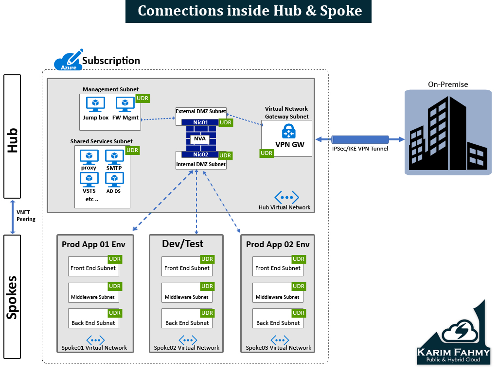
Today we will talk about the connectivity within the cloud which we can name it the connectivity inside the hub and spoke model
Before we start diving into deep , some points you have to consider 1st before you start implementing this model which are the following points :
- Azure Virtual Networks can have only 1 Virtual Network Gateway (and I will override this limitation in the next coming parts of that series)
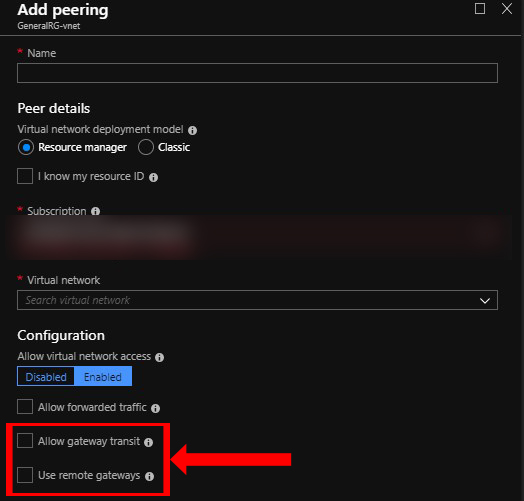
- When implementing VNET peering don’t enable the (Allow gateway transit & use remote gateway)
Step 1 : in building the hub & spoke (Network Infrastructure) :
you have 1st to define how your Architecture will look like and it depends on your business needs and also constrains so for example you have the below models:
- Hub & Spoke (Same region & Same subscription) à VNet peering
- Hub & Spoke (Same region & different subscription) à VNet Peering
- Hub & Spoke (Different region & Same subscription) à Global VNet Peering
- Hub & Spoke (Different region & Different subscription) à Global VNet Peering
- I will talk about model no.1 : Hub & Spoke (Same region & Same subscription) –> VNet peering
Note : In this model I assumed using VPN connection and not Express route just to start with simple example for declaring the concept easily for you .
So this model looks like as the following:
So this model looks like as the following:
Step 1 : Define Hub & Spoke network infrastructure
Step 1.1 : of all you need to know what services need to be in the shared services subnet and also in the management subnet and if any extra you have to define and also start defining how you want your spokes to look like and which workloads should be there if prod , or dev/test , or another systems depends on your case .
Step1.2 : choose address space that doesn’t overlap with your on-premise network or any other connected networks that might be connected later , then start dividing this Address space to different sub prefix like /25 or /26 or /27 or /28 what ever you see it suitable for your design then start writing them in excel sheet to have clear plan for building Virtual networks and also including subnets as you want .
Step 2: Build Hub and Spoke network infrastructure
A- Create Hub Virtual network
B- Create Hub Subnets (including the Ext & Int DMZ subnets )
C- Create Spokes Virtual Networks (as much as you want )
D- Create Spokes Subnets
Step 3: Create Routing Tables & Attach to subnets
– Create Routing Table and attach for each Subnet in the whole design (Except the Ext. & Int DMZ subnets as the NVA when deployed it will create its routing tables )
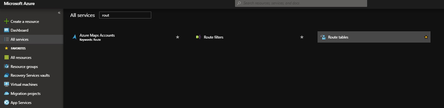
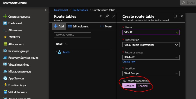
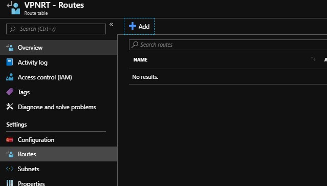
- Search in “All Services” for “Route tables”
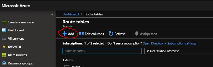
- Press add
- I named here an example routing table called (VPNRT) , note : When creating don’t forget to disable the BGP option
- After table has been created go to its left blade and select subnets:
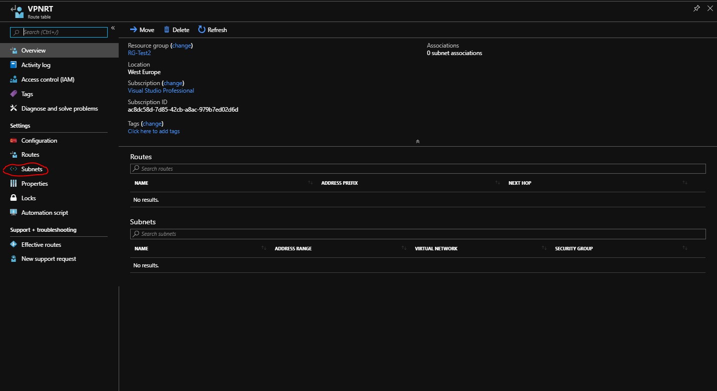
- Associate to the needed subnet
You will choose virtual network then choose the subnet you need to attach to it the table
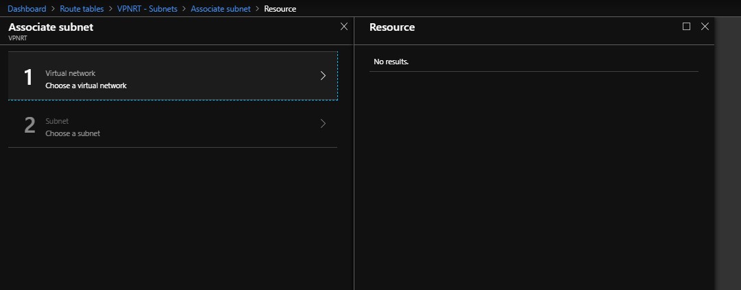
So after doing the previous steps for each subnet so at the end each subnet should be its own table.
Step 4 : Create Firewall Gateway NVA (Network Virtual appliance ) from the Azure Marketplace
It depends on your IT security team recommendation and which vendor they are used to, so you can find a lot of different vendors (Fortinet , Barracuda , Checkpoint etc .. ) with different licensing models.
Step 5 : Start defining (UDRs – User defined routes )
5.1 : so now after creating the whole Virtual networks and Subnets and attaching to each its own table , you can start defining the routes for each table depending on you scenario , but the main concept to point all traffic to the NVA then NVA will be the brain that will contain all FW rules checking who should be pass and who shouldn’t and to which destination and protocol & port .
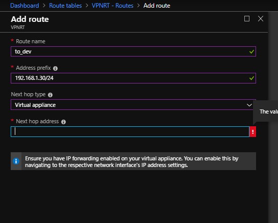
- Press on “Routes” on the left blade then press on “Add”
- Then put the route name you want and in the “Address prefix” put the destination you want to reach
- Then choose the next hop (in our case we will choose virtual appliance , and later we will take about the other options )
- Then put the IP Address of the Virtual appliance interface
adding to this I will talk in later episode about the Azure NSGs (Network security groups) which hardens your environment alongside with the NVA too .
that’s all for this time and the rest to be continued in the next episode ! .. stay tuned !
Thank you so much!
You manage to explain complex things in an easy manner.
Looking forward to read your next episodes about Hub&Spoke Azure networking.
It would be great to get a youtube video for all the 1-5 Azure Hub&Spoke episodes.
Thanks again!!
Thanks alot Bechor really appreciated , sure I will do this asap !